New Quasi-2-Level Operated Flying Capacitor Converter

© 2020 EPFL
The ETHZ-PES lab has developed a 40kV / 300kVA Quasi-2-Level Flying Capacitor Converter (Q2L-FCC) performing better than the conventional solution.
Current research at the Power Electronic Systems Laboratory (PES) of ETH Zurich in the context of SCCER- FURIES Work Package 3 targets a compact and highly integrated SiC-based Intelligent Power Module (IPM) for emerging Medium Voltage (MV) applications, such as high-power DC charging stations for ultra-fast charging of EVs or the DC-supply of future datacenters directly from the MVAC grid.
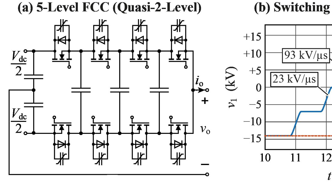
In the latest publication (see the article), a Quasi-2-Level Flying Capacitor Converter (Q2L-FCC, Fig.1 (a)) is proposed which features low switching losses at a reduced average dv/dt, reduced chip area, and low FC volume. Compared to a conventional 2-Level implementation with direct series-connected and simultaneously switched power transistors, the output voltage spectrum of the Q2L-FCC shows substantially lower harmonic energies at high frequencies, since the transistors are switched sequentially (staggered switching, Fig.1 (b)). Accordingly, the Q2L- FCC enables a reduction of the partial discharge amplitudes, mitigates the impacts of transformer/inductor/cable/load resonances, and allows for a decrease of dielectric losses (Fig.1 (c)) and features lower EMI emissions. Current research addresses the voltage balancing of the flying capacitors also in case of low output currents and no load.
Further information is accessible here.
Fig.1 (a) Proposed 40kV SiC half-bridge using a Q2L operated 5-Level Flying Capacitor Converter arrangement employing 4 stacked 10kV SiC MOSFETs as high-side and low-side super-switches. A virtual classical 2-Level bridge-leg is compared with the proposed Q2L-FCC: (b) switching transitions, (c) cumulative sum of the dielectric losses. The dielectric losses are computed for a typical capacitance of 200pF and a dissipation factor of 1%. The ratings are considered for 28 kV dc-link voltage and the system is operated at 20 kHz. In the final realization, the power circuit, isolated gate drive circuits (signal and power), and measurement, as well as monitoring circuits, will be combined to an Intelligent Power Module with galvanically isolated cooling baseplate.