Modelling realistic plasmonic nanoparticles

© 2014 EPFL
The enhancement of excitation and reemission of molecules in close proximity to plasmonic nanostructures is studied with special focus on the comparison between idealized and realistically shaped nanostructures. Numerical experiments show that for certain applications choosing a realistic geometry closely resembling the actual nanostructure is imperative, an idealized simulation geometry yielding significantly different results. Finally, a link between excitation and reemission processes is formed via the theory of optical reciprocity, allowing a transparent view of the electromagnetic processes involved in plasmon-enhanced fluorescence and Raman-scattering.
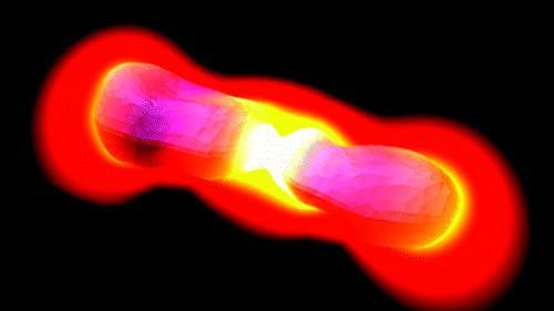
 In the past decade, one important application of plasmonic nanostructures has been the exploitation of their localized field enhancement for amplifying fluorescence and Raman scattering. This huge experimental body of work has been accompanied by many theoretical studies aiming at computing the near-field at the vicinity of such plasmonic nanostructures. Often these studies rely on idealized models for the nanostructures, such as the ideal dipole antenna shown on the top of the figure. In this study, we investigate the effect of some such simplifications often made in numerical analyses on the validity of their results, our main focus set on the difference between realistic and idealized objects. A model for a realistic object can be obtained from an SEM image, as shown in the left.
It is important to mention that in the far-field both antennas exhibit exactly the same behavior, with a resonance wavelength at λ=630nm. Their near-field however, can be significantly different, as shown in the following figure.

The previous figure shows the field intensity distribution of a resonantly excited nanoantenna (λ=630nm) mapped on a surface 1nm above the surface of the antennae. An ideal dipole (a) and a real antenna (b) are investigated. The field intensity is unwrapped using an equirectangular projection, as indicated on the left of the figure. Notice the strong field localization in the gap of the antennas and that not only does the magnitude of the field enhancement depend on the structure’s geometry, but so, too, does its distribution, dictating where the intensity will be maximal. This type of calculations enables engineering nansostructures with very specific enhancement properties. It also provides insights on the processing window required to achieved given performances for the optical nanostructures.
Besides concentrating incident light in “hot spots,” plasmonic structures can increase the efficiency of fluorescence and Raman scattering by enhancing the radiation of the re-emitted light to the far-field where it can be detected. In some studies, this mechanism is not considered with the focus set only on the localized enhancement of the incident field. In others, it is taken into account but at the cost of a completely new set of calculations, as the chosen methods are not capable of simulating both effects. The surface integral method used in this study is capable of simulating a structure’s response not only under plane wave illumination but also excited by a dipole source placed arbitrarily close to its surface. This makes it a suitable choice for simulating both the incident field enhancement and the radiation enhancement of light re-emitted from a fluorescent or Raman-active particle, as illustrated in the following figure.

The solid lines in this figure show the enhancement of the light radiated by a dipole source to the þz-direction, caused by the proximity to a rectangular (a-c) or realistic (d-f) plasmonic nanoantenna. The dipole source is located at three different points in the x-z-plane as indicated by the dots in the insets. Intensity enhancement is calculated for x-oriented (red lines) and z-oriented (green lines) dipole sources; the field is detected in the far-field at (x,y,z) = (0,0,106 nm) in x-polarization, parallel to the axis of the antennae. One can see that for a dipole located in the center of the gap (a,d) the intensity enhancement closely resembles the scattering cross section, the rectangular and realistic antennae displaying nearly the same behavior. The main difference, again, lies in the amplitude of the resonance peak, with the realistic case showing a slightly higher maximum enhancement. Moving away from the center of the gap, however, the similarity between both geometries quickly vanishes. Not only do the proportions between x- and z-polarizations differ but also the wavelengths at which the intensity is enhanced. The difference between polarizations is a direct effect of the shape of the scatterer: The coupling of a dipole to a metal surface strongly depends on the dipole’s orientation relative to the surface. The spectral deviation between idealized and realistic antennae is the effect of the breaking of symmetry relative to the x-y-plane. In case of symmetry (a,d) the spectrum is predominantly defined by the antennae’s geometry in x-direction (arm length and gap size), which is comparable for both geometries. Exciting the antennae away from their centers, other dimensions begin to play a role and the irregular shape of the realistic antenna causes its spectral response to be more complex than its idealized counterpart.
Check the corresponding publication: PDF External link: doi: 10.1021/nl1032588